Cable jointing connects two lengths of power cable so the joint carries the same current and voltage, and keeps water out, for the life of the circuit. On 11kV and 33kV routes, joints sit in joint bays: pits where cable lengths meet, built by the civils team so a qualified jointer can work clean, dry and safe.
Key points
- A cable route needs a joint wherever one length of cable ends: at the end of each drum, at changes of cable type and at the terminations.
- Joint bay positions are fixed by drum length, pulling tension and route bends, then adjusted for access and land.
- Electricity North West's ES400E4 gives nominal LV joint bay sizes of 0.7 m x 0.6 m to 1.6 m x 0.9 m, with about 300 mm dug below the cable.
- Pulling tension must stay within the manufacturer's limit and be shown automatically throughout the pull.
- Ducts are cleared with a mandrel and sealed before cable is pulled.
- Accredited contractors hold NERS scopes for cable laying and jointing, listed by voltage.
- Workmanship caused about two thirds of failures in one review of 100 failed MV terminations.
In this guide
- What is a cable joint, and what types are there?
- Why do cable routes need joints at all?
- What is a joint bay?
- Who does what: civils team or cable jointer?
- What competence does a cable jointer need?
- How is cable pulled into ducts?
- What conditions does jointing need?
- How are cables tested after jointing?
- Why do cable joints fail?
- How are joint bay positions chosen?
- Where Ground Utilities fits
- Frequently asked questions
- Planning a cable route?
What is a cable joint, and what types are there?
A cable joint restores everything the cable had before it was cut: the conductor connection, the insulation, the semiconducting screens that control electrical stress, the metallic screen or sheath, and the outer seal against moisture. The jointer rebuilds each layer by hand from a kit approved by the network operator.
| Accessory | What it does | Where you find it |
|---|---|---|
| Straight joint | Connects two lengths of the same cable type end to end | Every drum change along a route |
| Transition joint | Connects two different cable types, typically modern XLPE (cross-linked polyethylene) to older PILC (paper insulated lead covered) cable | Where a new circuit meets the existing network |
| Branch joint | Takes a tee off an existing cable | LV services and network tees at 11kV and 33kV |
| Termination | Ends the cable at switchgear, a transformer or an overhead line | Substations, switch rooms, pole tops |
| Link box | A sealed box giving access to cable sheath bonding connections | Next to joints on single-core circuits with special bonding |
Electricity North West's 33kV accessory specification (ES400J33, Issue 4, December 2025) lists XLPE straight joints alongside several XLPE to paper cable joints, because new circuits so often meet old ones.
What are link boxes and cross-bonding?
On a circuit of three single-core cables, load current induces a voltage in each cable's metallic screen. Sheath bonding, the way the screens are earthed, controls that voltage and the losses it causes. ES400E4 says that where single-core cables cannot be laid in trefoil (a tight triangle), the screen is earthed at one end only (single point bonding), keeping the induced voltage on long circuits within 65 volts. The detail is in ENA Engineering Recommendation C55.
Longer, higher-rated circuits may be cross-bonded. Each "major section" is split into three "minor sections" and the screens are swapped between phases at the joints, which reduces sheath losses and overvoltages (Xue et al., IEEE Transactions on Power Delivery, 2023). The swap is made in a link box, which PD Devices and other makers fit with sheath voltage limiters against overvoltages from lightning, faults and switching. A cross-bonded route needs link box positions designed into the joint bays from the start.
Why do cable routes need joints at all?
Cable comes on drums of finite length, and only so much can be pulled through a duct before the tension damages it. Every section ends in a joint.
The joint bay report for the AQUIND interconnector ties bay spacing to "the lengths of cables that can fit on a drum and pulling tension limits", and notes that more or sharper bends reduce the length that can be safely pulled. That project is an HVDC (high voltage direct current) link, and the same two limits apply on an 11kV or 33kV route.
What is a joint bay?
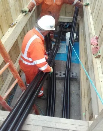
A joint bay is a temporary excavation, sized to the joints it will hold, where cable sections are pulled in, jointed and tested. Afterwards the bay is backfilled and reinstated, and the joints stay in the ground.
How big is a joint bay?
Size depends on voltage, the number of circuits and the joint kit. Network operators publish guidance; the joint shells set the final size.
| Bay type | Published dimension | Source |
|---|---|---|
| LV joint bay JB1 | 0.7 m long x 0.6 m wide | ENWL ES400E4, Table 5 |
| LV joint bay JB2 | 1.4 m x 0.8 m | ENWL ES400E4, Table 5 |
| LV joint bay JB3 | 1.6 m x 0.9 m | ENWL ES400E4, Table 5 |
| 6.6kV / 11kV joint bay | Minimum length and width by drawing; at least 300 mm clearance below the cable | ENWL ES400E4, Appendix C |
| Any joint hole at energisation | 300 mm deeper than the deepest cable or duct | ENWL joint bay excavation guidance |
| HVDC joint bay (for scale) | Excavation about 15 m x 3 m per circuit | AQUIND joint bay feasibility report |
At 33kV the bay follows the joint layout. National Grid Electricity Distribution's ST:CA3A shows the three single-phase joints offset along the bay, and its ST:CA6A gives recommended 33kV joint bay drawings. Ask the network operator for the drawing that applies to your scheme.
How is a joint bay built?
- Set out. Re-measure the bay position against the design and the services survey.
- Excavate and support. HSE says no ground can be relied on to stand unsupported in all circumstances. Plan shoring or battering before digging and inspect at the start of each shift (CDM 2015 Regulation 22).
- Dig below the cable. ES400E4 asks for space for jointing and shell closure, typically 300 mm below the cable, with steps or a slope for access.
- Form a floor. Cables must lie straight and level, supported from the bay floor to carry the joint. On large bays a concrete slab gives the jointer what the AQUIND report calls a level, rigid and safe working platform.
- Manage water. Where water keeps getting in, ES400E4 calls for a sump in the lowest corner to bail or pump from.
- Protect the area. ENWL rejects joint holes without shoring, signs and barriers, or safe access, and wants spoil cleared from the edge.
How is a joint bay backfilled and marked?
ES400E4 bars backfilling near a fresh joint until any resin has cured solid to the touch. Cables and joints are bedded and blinded in the specified surround, 100 mm above the cable in streets, and foamed concrete is not used around cables unless approved. Warning tape goes no more than 100 mm above each cable, route marker posts go in on private land, and highway openings are reinstated to the national reinstatement specification. As-constructed records of every cable and joint are drawn up first, while everything is still visible.
Who does what: civils team or cable jointer?
The civils contractor builds the route and the bays; the jointer makes the joints. They are often different companies, and problems start at the handover.
| Task | Usually done by |
|---|---|
| Trenching, ducting, draw ropes, duct proving | Civils / cable laying team |
| Joint bay excavation, shoring, sump, floor | Civils team |
| Cable pulling from drum to bay | Cable laying team, with the jointer often present |
| Jointing, terminating, sheath bonding | Accredited jointer |
| Sheath and pressure testing | Jointer, test engineer or the network operator |
| Bedding, backfill, tape, reinstatement | Civils team |
ES400E4 says that where the cable installer is not the jointer, the jointer's facilities must be agreed between the two. Put tent, lighting, pumping and power in writing before the first bay opens.
What competence does a cable jointer need?
Look for accreditation at company level and a registration or authorisation at individual level.
The National Electricity Registration Scheme (NERS), run by LRQA, accredits independent connection providers (ICPs) for contestable work. Its published categories separate cable laying (LV, 11kV, 33kV, 132kV) from cable jointing (dead LV, live LV, 11kV, 33kV, 132kV) and civil engineering works. A contractor can hold laying without jointing, so check scope and voltage on the certificate; our article on what ICP and NERS mean for a new connection explains how.
For individuals, the Energy and Utility Skills Register (EUSR) runs a three-year Cable Jointer registration. It needs an in-date SHEA Power registration plus a jointer apprenticeship, a City & Guilds underground cables certificate, a DNO competent or authorised person certificate, or a NERS certificate of competence.
Network operators add their own checks: ES400E4 requires jointers to pass a trade test, where applicable, before working on Electricity North West's network.
How is cable pulled into ducts?
The cable is pulled off a drum at one bay, through the duct, by a winch at the next bay, with the tension measured throughout.
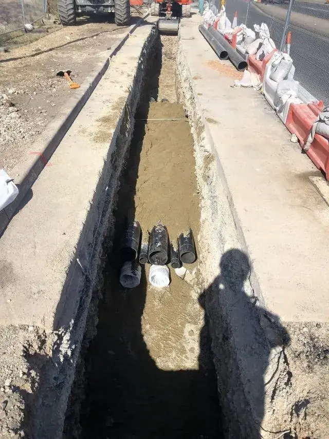
- Prove the duct. UK Power Networks wants ducts cleared of all obstructions with duct-clearing mandrels and sealed after laying, and may ask for a short length of cable to be drawn through as proof.
- Fit the draw rope. Leave a non-corrosive draw rope in each duct.
- Set up drum and winch. The drum sits on a stand at one end. Rollers at the bay mouth guide the cable into the duct.
- Pull with measured tension. ES400E4 says mechanical pulling tension must not exceed the manufacturer's value and must be indicated automatically throughout the pull. Nexans' rule of thumb is 30 N/mm² of conductor for aluminium and 50 N/mm² for copper; the cable datasheet governs.
- Respect bending radius. ES400E4 tabulates minimum bending radii; for its 11kV single-core cables these are 15 to 20 times the cable diameter.
- Watch the temperature. If the working or storage area has been below 1°C in the previous 24 hours, the manufacturer's cold-weather guidance applies.
- Cap the ends. Every cut end is capped to keep moisture out, including drum ends.
What conditions does jointing need?
Jointing needs a dry, clean, well-lit space. ES400E4 asks for a working area that is clean, safe, adequately lit and as far as reasonably practical free from flooding, with special care to keep out dirt and contamination. National Grid describes putting a temporary tent over its jointing bays to keep the work clean and dry. Moisture and dirt trapped in a joint are a leading cause of failure.
How are cables tested after jointing?
New HV cables are tested before connection, to the network operator's requirements. UK Power Networks lists pressure tests and sheath tests for HV cables among its pre-connection tests on HV contestable works.
A sheath test checks that the outer sheath survived pulling and backfill. A pressure test, or withstand test, stresses the main insulation above its service voltage. For XLPE cable this can be done with a very low frequency (VLF) AC test set at 0.1 Hz. Test-set maker Seba KMT, part of Megger, states that DC testing is not applicable to PE and XLPE cables. Test voltages and durations come from the operator's own commissioning specification, so confirm them at design stage.
Why do cable joints fail?
Most joint failures trace back to how the joint was made. In a review of 100 forensic reports from 2011 to 2015, EA Technology found workmanship behind about two thirds of failures in MV terminations, with manufacturing defects a much smaller share. The same review named poor semiconducting screen cutbacks as the number one problem in the UK.
| Cause | What goes wrong |
|---|---|
| Screen cutback errors | A poor cut in the semiconducting layer, the top UK problem in the EA Technology review |
| Contamination | Dirt, moisture or semicon residue left on the insulation surface |
| Poor moisture seals | Water tracks along the sheath into the joint |
| Disturbance before cure | Backfilling near uncured resin breaks the moisture seals |
| Mechanical strain | Cables not straight, level and supported load the joint |
| Damaged sheath | Pulling or backfill damage lets water reach the screen |
A flooded bay, an early backfill or a badly supported cable can undo good jointing.
How are joint bay positions chosen?
The designer starts with drum lengths and pulling calculations, then moves bays to where they can be built and reached.
- Pulling limits: the maximum section length for the cable size, reduced for bends.
- Access: room for the drum delivery vehicle and stand at one end, and the winch and anchor at the other.
- Highway impact: the AQUIND planning documents commit to joint bays off carriageway unless unavoidable, to reduce traffic management.
- Water: avoid low spots that flood, since the bay has to stay as far as reasonably practical free from flooding while the jointer works.
- Crossings and fewer bays: on our 5 x 33kV route in North London, which crossed waterways and major road junctions, bespoke cable lengths reduced the number of joint bays.
Every joint is a cost and a possible fault, so fewer is better.
Where Ground Utilities fits
Ground Utilities is a NERS accredited power and civils contractor based in Cottenham, Cambridgeshire. Our HV cable projects include:
- HV cable installations in Cambridgeshire: 2 x 33kV circuits over approximately 25 km between a DNO substation and a new client substation, fully ducted, with 45 joint bays, each fully reinstated after jointing.
- 5 x 33kV with fibre optic, North London: about 53,000 m of 33kV and fibre cable in a double-stacked duct route, with bespoke cable lengths used to reduce joint bay construction.
- Thetford cable route: a 6 km dual 33kV and fibre route with an HDD crossing beneath a local river.
- Dunmow and Whittle Laboratory: 33kV and 11kV cable routes with associated ducting.
Ground Utilities holds full NERS approval for cable laying at LV, 11kV, 20kV, 33kV, 66kV and 132kV, and for civil works, with all six distribution network operators, including UK Power Networks (LRQA NERS register, checked November 2026). Our NERS approval does not include a cable jointing scope. On the Cambridgeshire route above we built the 45 joint bays and fully reinstated each one after jointing.
See also our multi-utility services, civil construction and accreditations pages, and related guides on avoiding utility strikes, underground utility colour codes, horizontal directional drilling, UKPN G81, section 38, 104 and 278 agreements and battery storage site groundworks.
Frequently asked questions
What is cable jointing?
Cable jointing is connecting two lengths of power cable, or ending one at equipment, so the connection matches the cable's rating and stays sealed against moisture. On 11kV and 33kV cable the jointer rebuilds each layer by hand from an approved kit.
What is a joint bay?
A joint bay is an excavation along a cable route where two cable sections are pulled in and jointed. The civils team digs, supports and drains it, the jointer makes the joints, and the bay is then backfilled and reinstated with the joints left buried.
How far apart are joint bays?
It depends on drum length, cable size and bends, because each section must be pulled within the cable's tension limit. The designer calculates each section, and bespoke cable lengths can cut the number of bays.
How big is an 11kV or 33kV joint bay?
Size depends on the joint kit and the number of circuits. Electricity North West publishes nominal LV bays from 0.7 m x 0.6 m to 1.6 m x 0.9 m and asks for about 300 mm of depth below the cable. HV bays are longer and follow the network operator's drawing for the scheme.
What qualifications does a cable jointer need?
Contractors doing contestable work need NERS jointing accreditation at the right voltage. Individual jointers can register with EUSR's Cable Jointer scheme using an apprenticeship, a City & Guilds underground cables certificate, or a DNO or NERS competence certificate.
What is a transition joint?
A transition joint connects two different cable types, most often new XLPE cable to older paper insulated lead covered cable. It is common where a new circuit connects to an existing network.
How are HV cables tested after jointing?
New HV cables get a sheath test on the outer sheath and a pressure test on the main insulation, which for XLPE cable can use very low frequency AC. The network operator sets the voltages and durations.
Why do cable joints fail?
Most failures come from workmanship: poor screen cutbacks, contamination, weak moisture seals, or disturbing the joint before resin has cured. Wet, dirty or unsupported joint bays make all of these more likely.
Planning a cable route?
If you are planning an 11kV or 33kV route for a development, solar farm or battery site, involve the civils contractor before the joint bay positions are fixed. We can review drum lengths, crossings and access with your designer and price the route with the bays where they can actually be built. Call +44 1223 423918, email info@ground-utilities.co.uk, or use our contact page.
Sources
- Electricity North West, "ES400E4 Installation and Repair of LV and 6.6/11kV Underground Cables and the Restoration of Excavated Areas", Issue 12, June 2024: enwl.co.uk
- Electricity North West, "Guidance for Joint Bay Excavation": enwl.co.uk
- Electricity North West, "ES400J33 33kV Solid Insulated Cable Accessories", Issue 4, December 2025: enwl.co.uk
- National Grid Electricity Distribution (formerly Western Power Distribution), "ST:CA3A" 33kV jointing configurations, March 2017: commercial.nationalgrid.co.uk
- National Grid Electricity Distribution, "ST:CA6A/7 Underground Cable Installation", June 2021: commercial.nationalgrid.co.uk
- National Grid, "Installing 400,000 volt cable under Mendip Hills AONB" (Hinkley Connection): nationalgrid.com
- UK Power Networks, Connections library, "3.2 Ducts", V2 April 2024: library.ukpowernetworks.co.uk
- UK Power Networks, Connections library, "4.1.16 Pre and post-connection tests for high voltage contestable works", V2 April 2024: library.ukpowernetworks.co.uk
- LRQA, "Utility Schemes Factsheet GB" (NERS categories of accreditation), 2021: assets.lrqa.com
- EUSR, "Cable Jointer" scheme: eusr.co.uk
- Health and Safety Executive, "Excavations": hse.gov.uk
- AQUIND Limited / WSP, "UK Joint Bay Feasibility Report", document 7.9.26, January 2021 (Planning Inspectorate, EN020022): infrastructure.planninginspectorate.gov.uk
- Thorne & Derrick, "11kV Cable Pulling" (pulling force guidance attributed to Nexans): powerandcables.com
- H. Xue, J. Mahseredjian, J. Morales and I. Kocar, "Analysis of Cross-Bonded Cables Using Accurate Model Parameters", IEEE Transactions on Power Delivery, vol. 38, no. 1, 2023: ira.lib.polyu.edu.hk
- PD Devices, "Link Box Series LB19/28OD55, LB21/28OD37 and LB21/28OD55" datasheet, revision vPD2, 2019: powerandcables.com
- EA Technology, "MV Cable Termination Failure Prevention", W. Higinbotham, March 2019: eatechnology.com
- Seba KMT (Megger), "VLF Test System 20 kV" datasheet: atecorp.com
- Ground Utilities, "HV Cable Installations": ground-utilities.co.uk
- Ground Utilities, "5 x 33kV with Fibre Optic": ground-utilities.co.uk
- Ground Utilities, "Thetford Cable Route & Civil Build": ground-utilities.co.uk
- Ground Utilities, "Dunmow" and "Whittle Laboratory" project pages: ground-utilities.co.uk and ground-utilities.co.uk
- Ground Utilities, "ICPs and NERS: what they mean for your new connection": ground-utilities.co.uk
- LRQA, NERS register entry for Ground Utilities Ltd, checked 3 November 2026: lrqa.com