Distribution cable routes in the UK commonly run at 11kV, 33kV or 132kV. Each step up in voltage changes what goes in the ground, even where the trench looks the same from the road.
This guide sets out industry practice, based on published specifications from the distribution network operators (DNOs). Electricity North West's specifications are used as the worked example because they publish separate documents for 11kV, for 33kV and 132kV, and for 132kV accessories. Your own DNO's specification always governs your scheme.
Key points
- In law, anything above 1,000 V AC between phases is high voltage (ESQCR 2002, regulation 1).
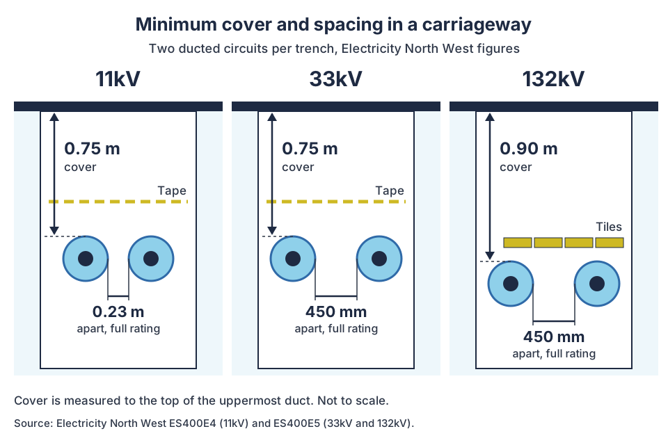
- Electricity North West asks for 0.75 m of cover over 11kV cable in carriageways, 0.75 m over 33kV and 0.90 m over 132kV.
- Circuits at 33kV and 132kV need 450 mm between them for full rating. At 11kV the figure is 0.23 m.
- At 132kV, Electricity North West wants protection tiles over ducted cables as well as direct buried ones. At 11kV, tape is enough.
- A typical 33kV joint bay is about 4 m by 2 m, and can stretch to 5 m.
- At 132kV, link boxes for sheath bonding sit in covered pits or above ground. Joints must meet IEC 60840.
In this guide
- What do 11kV, 33kV and 132kV mean?
- Which cables are used at each voltage?
- How deep is each voltage laid?
- How far apart must circuits be?
- What protection goes over the cable?
- What backfill goes around HV cables?
- How do joint bays change with voltage?
- Why does sheath bonding matter more at 132kV?
- How are HV cables tested before energising?
- Who can lay and joint each voltage?
- 11kV vs 33kV vs 132kV at a glance
- Where Ground Utilities fits
- Frequently asked questions
- Planning an 11kV, 33kV or 132kV route?
- Sources
What do 11kV, 33kV and 132kV mean?
The number is the nominal voltage between phases: 11,000, 33,000 or 132,000 volts. The Electricity Safety, Quality and Continuity Regulations 2002 (ESQCR) define low voltage as above 50 V and up to 1,000 V AC between phases. High voltage is any voltage above that.
So 11kV, 33kV and 132kV are all high voltage in law. On site, people often say "HV" for 11kV and "EHV" for 33kV and above, but those terms vary by network operator.
Cable ratings are often written U0/U (Um):
- U0 is the voltage between conductor and earth.
- U is the voltage between phases.
- Um is the highest voltage the equipment is designed for.
Electricity North West gives its 132kV system as 76/132 (145) kV, with a 650 kV impulse withstand voltage (ES400CS132). Its 33kV accessories are specified for Um = 36 kV.
Which cables are used at each voltage?
Modern distribution cables are usually insulated with XLPE, cross-linked polyethylene. Older circuits may be paper insulated, and Electricity North West's specifications still cover gas-filled 33kV and oil-filled 132kV cables.
| Voltage | Common British Standards and specifications | Notes |
|---|---|---|
| 11kV | BS 7870-4 series; BS 6622:2007 | Three-core or single-core |
| 33kV | BS 7870-4 series (for example 4.11, single-core lead sheathed); BS 6622:2007 | Often three single cores laid in trefoil |
| 132kV | DNO specifications, for example Electricity North West ES400C14 for XLPE cable; accessories to IEC 60840 | Single-core; cable system designed as a whole with its joints and bonding |
BS 6622:2007 covers armoured cables with thermosetting insulation from 3.8/6.6 kV to 19/33 kV. BSI describes them as rated for a 90°C maximum continuous conductor temperature and 250°C in a short circuit. BS 7870-4.11 covers 19/33 (36) kV single-core cables with XLPE insulation and a lead alloy sheath.
The cables get bigger and heavier as voltage and rating rise. On our Indian Queens private wire, each 33kV circuit is three 630/800 mm² aluminium XLPE cores laid in trefoil.
How deep is each voltage laid?
Under Electricity North West's specifications, minimum cover in a carriageway is 0.75 m at 11kV and 33kV and 0.90 m at 132kV. Cover is greater in good agricultural land, and other DNOs set their own figures.
Depth of cover is measured to the top of the uppermost cable, joint or duct. These are Electricity North West's minimums, with SSEN's figures for comparison.
| Voltage | Footway or verge | Carriageway | Good agricultural land | Source |
|---|---|---|---|---|
| 11kV | 0.60 m | 0.75 m | 0.90 m | ENWL ES400E4, Table 2 |
| 33kV | 0.75 m | 0.75 m | 0.91 m | ENWL ES400E5, Table 5.4.1 |
| 132kV | 0.90 m | 0.90 m | 0.91 m | ENWL ES400E5, Table 5.4.1 |
| 11kV | 600 mm | 750 mm | 1,000 mm | SSEN trenching guide |
| 33kV | 800 mm | 900 mm | 1,100 mm | SSEN trenching guide |
A few rules sit alongside the table:
- Electricity North West allows a cable to go up to 0.3 m deeper than the minimum, never shallower.
- At 33kV, cover in footways, verges and carriageways can drop to 600 mm if approved high-strength (1500 N) PVC duct is used.
- On railway land, 33kV and 132kV cables need 1.25 m from the top of the rail to the top of the cable. No cable may be within 2 m of a rail.
- Where the minimum cannot be met, Electricity North West requires extra mitigation under its policy for shallow cables.
- SSEN adds the duct size and 75 mm of sand bedding to the minimum to get the dig depth.
The law behind these figures is ESQCR regulation 14. It requires a cable to be kept at a depth, or otherwise protected, to avoid damage or danger from foreseeable uses of the land.
How far apart must circuits be?
Electricity North West asks for 450 mm between 33kV or 132kV circuits, and 0.23 m between 11kV cables, for full rating. Cables heat each other. Closer spacing means a lower rating, so the network operator sets a spacing for full rating.
| Voltage | Spacing for full rating | If spacing cannot be met | Source |
|---|---|---|---|
| 11kV | 0.23 m (plus or minus 10%) | De-rating factor applied to both cables | ENWL ES400E4, Table 3.1 |
| 33kV | 450 mm between outer sheaths or ducts | 10% de-rating for two circuits, agreed in advance | ENWL ES400E5, Table 5.4.2 |
| 132kV | 450 mm between outer sheaths or ducts | 10% de-rating for two circuits, agreed in advance | ENWL ES400E5, Table 5.4.2 |
Three more spacing rules apply:
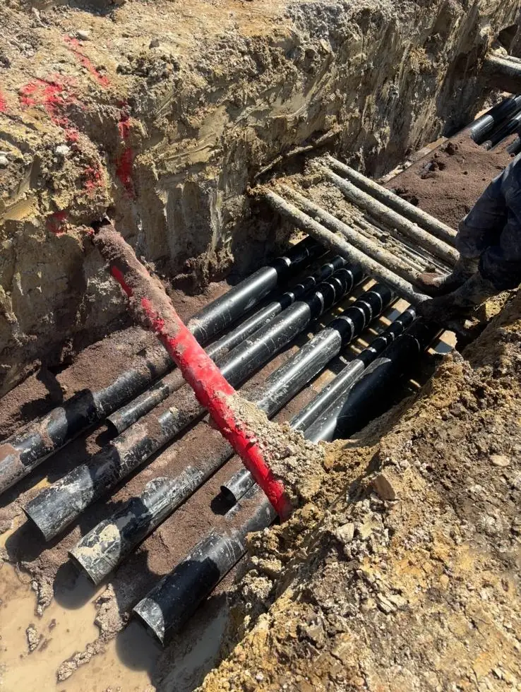
- Spacing is measured between the outer sheaths or ducts, not between cable centres.
- Where possible, Electricity North West wants at least 50 mm between power cables and metallic pilot or auxiliary cables.
- Where two circuits must sit closer, the engineer may also ask for extra mechanical protection. That stops a dig on one circuit damaging the other.
What protection goes over the cable?
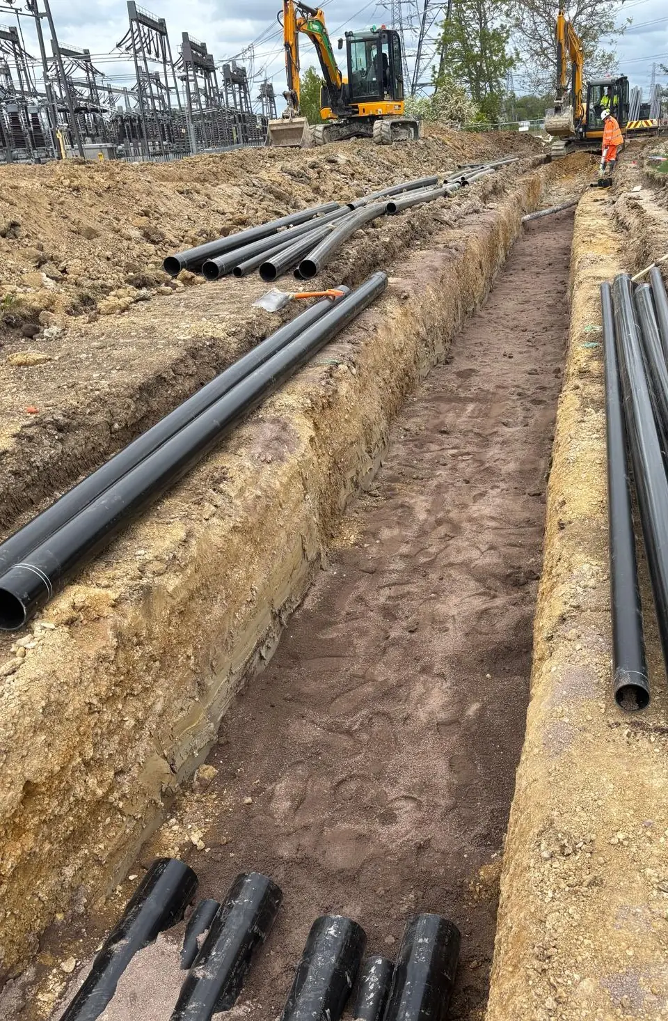
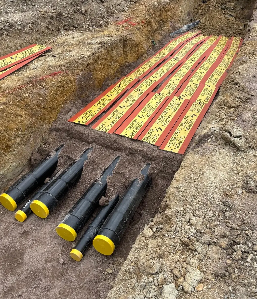
ESQCR regulation 14 requires cables with conductors not connected to earth to be protected, marked or indicated. It allows a duct, tiles, tape or another suitable device. Our cable ducting guide covers duct types and colours.
Electricity North West uses each option differently by voltage:
| Voltage | Direct buried | Ducted | Drilled HDPE duct |
|---|---|---|---|
| 11kV | Warning tape | Warning tape | Duct only |
| 33kV | Protection tile | Warning tape | None |
| 132kV | Protection tile | Protection tile | None |
Where tiles are used, the rules vary by DNO:
- ES400E5: tiles go at least 100 mm above the top cable.
- ES400E5: they overlap the cables by at least 50 mm each side.
- ES400E5: the engineer may add steel plates, extra tiles or steel ducts at bridges, joint positions and utility crossings.
- SSEN asks for tape or tiles 150 mm above the apparatus, carrying SSEN branding.
What backfill goes around HV cables?
The designer specifies the backfill around HV cables, because it controls how well a buried cable sheds heat into the soil and so how much current it can carry.
On higher-rated 33kV and 132kV routes, the designer often calls for a thermal backfill around the cables. An example is the illustrative trench sections in a recent Planning Inspectorate application (EN010162). They show a thermal compound, "cement bound sand or similar", around 33kV and 132kV cables, with well compacted, thermally suitable backfill above.
Check three things before you dig:
- the bedding and surround material, and its thickness;
- whether a thermal compound is needed, and where it stops;
- what may go back above it. Electricity North West's reinstatement materials are set in ES400R5.
How do joint bays change with voltage?
Joint bays grow with voltage, because the joints get longer and the cables stiffer.
| Voltage | Typical joint bay | Source |
|---|---|---|
| 11kV | Sizes by drawing, with about 300 mm dug below the cable for jointing and shell closure | ENWL ES400E4, Appendix C |
| 33kV | About 4 m by 2 m, up to 5 m long depending on cable size and joint | ENWL ES400E5, 6.4 |
| 132kV | Set by the joint maker and the bonding design | ENWL ES400CS132 |
Electricity North West adds detail at 33kV:
- Where specified, bays get close-boarded timber shuttering and a level hard standing.
- A sump goes in the lowest corner where water keeps getting in.
- If joints are laid at 750 mm, they must be fully encapsulated in resin.
- If joints are at 900 mm or more, or inside a secure substation compound, they may use reinforced heat shrink sleeves instead.
At 132kV, Electricity North West prefers joint designs that do not need long joint bays to fit pulling tools. Its 132kV joints come as straight joints and screen sectionalising joints, for bonding. Our cable jointing and joint bays guide covers bay construction in detail, and our joint bay construction page covers what we build.
Why does sheath bonding matter more at 132kV?
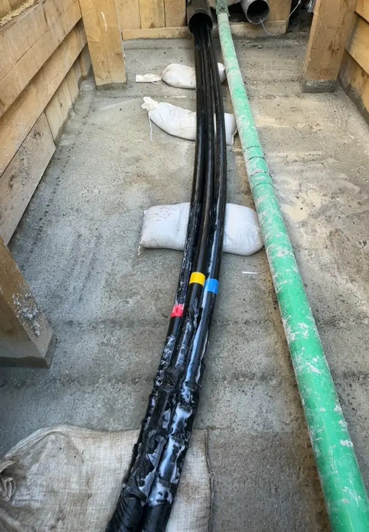
At 132kV the sheath bonding is designed into the cable system from the start, with link boxes, sheath voltage limiters and bonding leads, and the link boxes need their own pits on the route. A single-core cable carrying load induces a voltage in its own metallic screen. How the screens are earthed, the bonding, controls that voltage and the losses it causes.
Electricity North West handles it differently by voltage:
- At 11kV, it lays single cores in trefoil where it can. If trefoil is not possible, it uses single point bonding and checks that induced screen voltage on long circuits stays within 65 V (ES400E4).
- At 132kV, bonding is designed in from the start. ES400CS132 covers:
- link boxes, metal housings for the bonding connections, made and tested to ENA ER C55/6 and BS 7912;
- sheath voltage limiters (SVLs), fitted inside earthed link boxes where the bonding design needs them;
- bonding leads between the joints and the link boxes.
Link boxes can sit above ground or in a covered pit. That pit is permanent civils work on the route, with its own cover and frame, so its position belongs on the drawings from the start.
How are HV cables tested before energising?
New HV cables are tested before they are connected. UK Power Networks lists pressure tests and sheath tests for HV cables among its pre-connection tests for HV contestable works.
What that means on the route:
- A sheath test checks that the outer sheath survived pulling and backfill.
- A failed sheath test can mean digging the route up again. That is why bedding, surround and careful backfilling matter to the civils team.
- Electricity North West sets its commissioning tests in CP319 for 33kV and 132kV.
- Test voltages and durations come from the network operator. Testing is done by the jointer, a test engineer or the operator.
Who can lay and joint each voltage?
The National Electricity Registration Scheme (NERS), run by LRQA, accredits contractors for contestable work. Cable laying and cable jointing are separate scopes, each listed by voltage.
A contractor can hold laying approval at a voltage without jointing approval. Our guide NERS, ICPs and IDNOs explained shows how to read a certificate. Before you appoint, check:
- ☐ the scope on the certificate: cable laying, jointing, or both;
- ☐ the voltage each scope covers;
- ☐ on Electricity North West's 33kV and 132kV network, current Lloyd's Register certificates for cable installation work;
- ☐ that jointers have passed Electricity North West's trade test, where applicable, before working on its network.
11kV vs 33kV vs 132kV at a glance
This table sums up what changes on the route at each voltage, using Electricity North West's figures where a DNO figure is given.
| On the route | 11kV | 33kV | 132kV |
|---|---|---|---|
| Cover in carriageway (ENWL) | 0.75 m | 0.75 m | 0.90 m |
| Cover in footway or verge (ENWL) | 0.60 m | 0.75 m | 0.90 m |
| Spacing for full rating (ENWL) | 0.23 m | 450 mm | 450 mm |
| Marker over ducted cable (ENWL) | Tape | Tape | Tiles |
| Typical joint bay | Small, by drawing | About 4 m by 2 m, up to 5 m | Set by joint and bonding design |
| Bonding equipment | Single point bonding where needed | Varies by design | Link boxes, SVLs and bonding leads |
| Cable standards | BS 7870-4, BS 6622 | BS 7870-4, BS 6622 | DNO specification, accessories to IEC 60840 |
Where Ground Utilities fits
Ground Utilities Ltd is a civils and cable laying contractor based at Highdrove Farm, Cottenham, Cambridgeshire, working across England and Wales. We hold full NERS approval for civil works and for cable laying from LV to 132kV. It covers LV, 11kV, 20kV, 33kV, 66kV and 132kV, with all six distribution network operators.
In November 2026 the LRQA NERS register listed 543 accredited providers. Forty-five of them, Ground Utilities among them, held full approval for cable laying at 132kV.
Routes we have built at each voltage include:
- 11kV: the Whittle Laboratory cable route in Cambridge, with its ducting.
- 33kV: the Cambridgeshire HV cable installation, two 33kV circuits and fibre over about 25 km with 45 joint bays. In Cornwall, the Indian Queens private wire, about 46 km of 33kV cable with 19 joint bays, is in progress.
- 132kV: on a 49.9MW battery storage facility in Cambridgeshire, the electrical ducting and cable installation for the 132kV and 33kV cables.
We build the route and install the cable: trenching, ducts, joint bays, cable pulling and reinstatement. Our NERS approval does not include jointing or design.
We do not joint or terminate cables, make the final live connection, or apply for connections. The network operator, the client's connection provider or the designer does those. See our HV and LV cable installation service.
Frequently asked questions
What is the difference between 11kV, 33kV and 132kV cable?
The voltage each carries between phases. Higher voltage cables are laid deeper, wider apart and with more protection. At 132kV, joints and sheath bonding are designed as one system with the cable.
How deep is a 33kV cable buried?
Electricity North West asks for at least 0.75 m of cover in footways and carriageways and 0.91 m in good agricultural land. SSEN asks for 800 mm, 900 mm and 1,100 mm. Check your own DNO's specification.
How deep is a 132kV cable buried?
Electricity North West asks for at least 0.90 m of cover in footways, verges and carriageways and 0.91 m in good agricultural land. On railway land it asks for 1.25 m below the top of the rail.
What is XLPE cable?
XLPE is cross-linked polyethylene, the insulation used on most new UK distribution cables. BS 6622 covers armoured XLPE and EPR insulated cables from 3.8/6.6 kV to 19/33 kV.
Is 11kV high voltage?
Yes. The ESQCR treat anything above 1,000 V AC between phases as high voltage, so 11kV, 33kV and 132kV are all high voltage.
How far apart should 33kV circuits be?
Electricity North West asks for 450 mm between the outer sheaths or ducts of two 33kV circuits. Closer spacing means about 10% de-rating for two circuits, agreed with the engineer in advance.
Why are single-core cables laid in trefoil?
Trefoil, a tight triangle of three single cores, is the standard layout in Electricity North West's specifications. Where trefoil is not possible, ES400E4 calls for single point bonding instead, with limits on the induced screen voltage.
What is a link box?
A sealed metal box giving access to the sheath bonding connections on single-core HV circuits. At 132kV it may also hold sheath voltage limiters. It sits above ground or in a covered pit.
Planning an 11kV, 33kV or 132kV route?
Bring the civils contractor in while the trench sections, joint bay positions and crossings are still being drawn. Call 01223 423918 or email info@ground-utilities.co.uk.
Sources
- The Electricity Safety, Quality and Continuity Regulations 2002, regulation 1 (interpretation) (legislation.gov.uk, 2002)
- The Electricity Safety, Quality and Continuity Regulations 2002, regulation 14 (legislation.gov.uk, 2002)
- ES400E4 Installation and Repair of LV and 6.6/11kV Underground Cables and the Restoration of Excavated Areas, Issue 12 (Electricity North West, 2024)
- ES400E5 Installation and Repair of Underground Cables Operating at 33kV and 132kV, Issue 9 (Electricity North West, 2024)
- ES400CS132 Cable Systems, Including Joints, Terminations, Associated Sealants and Components for use on 132kV Underground Networks (Um = 145kV), Issue 3 (Electricity North West, 2024)
- New connections: Mains trenching and cable laying guide (SSEN)
- BS 6622:2007 Electric cables. Armoured cables with thermosetting insulation for rated voltages from 3.8/6.6 kV to 19/33 kV (BSI, 2007)
- BS 7870-4.11:2011+A1:2016 Single-core 33 kV lead sheathed cables (BSI, 2016)
- 4.1.16 Pre and post-connection tests for high voltage contestable works (UK Power Networks)
- EN010162 ES Figure 5.9 Illustrative Cable Trench Cross Section (Planning Inspectorate)